
ev3.NET at Brick Cascades 2017
Last year we showed off our Lego robot at the Brick Cascades Lego convention in Portland Oregon. It was so much fun we had to go back this year. Of course we also had to make a few improvements to our creation so it would be more interesting to look at and even more useful for teaching kids about robotics and computer programming.
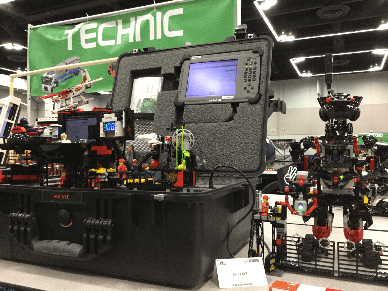
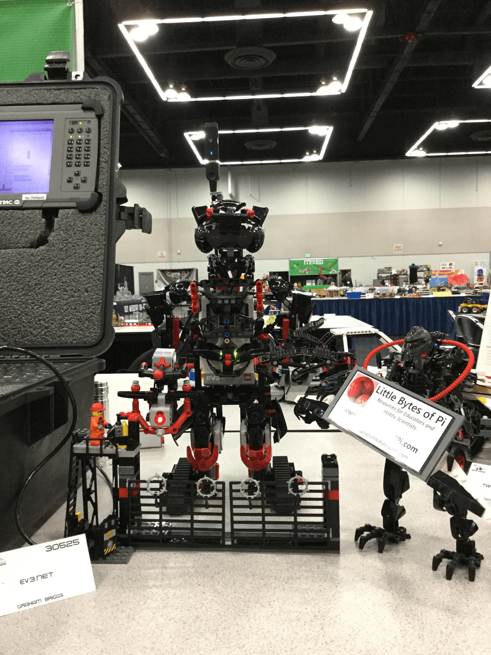
A robot this awesome should travel in style, so we made a neat carrying case for it

When it is all put together, you can drive the robot with an XBox remote, and LED lights on the display will react to the readings from the robot’s sensors.
The system includes a number of components that all fit into the robot’s box.
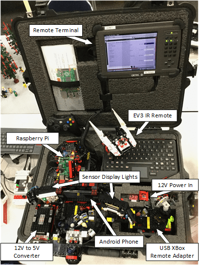
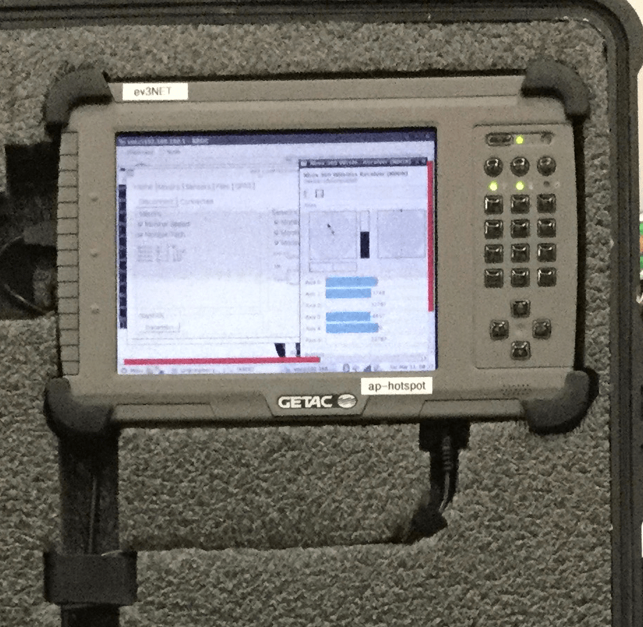
The case includes an old tablet computer that can run our ev3 Control Panel software, or it can be a remote terminal when we are running the software on the Raspberry Pi to control the robot.
The Raspberry Pi is used with a Wi-Fi dongle to create an ad-hoc wireless network. The ev3.NET robot connects to this network so you can control it by sending commands over Wi-Fi. The remote terminal and Android phone are also connected to this WiFi network so they can mirror the Raspberry Pi’s display.
At the heart of the system is a Raspberry Pi running our ev3.NET control software. It is powered from a 3.7 V lithium ion battery mounted under the frame.

There is a charging circuit board so you can run the PI and charge the battery at the same time.

The goal of the project was to build something to demonstrate the behavior of the robot’s sensors and how you can use the sensor readings in your robot control code.
For more examples of how the sensor display responds to the robot’s sensor readings, see our page here:
The sensor display system includes a MCP23017 pin expanding chip to run the seven segment display and a PCA9685 PWM chip to run additional circuits including the RGB LED for the color light display.
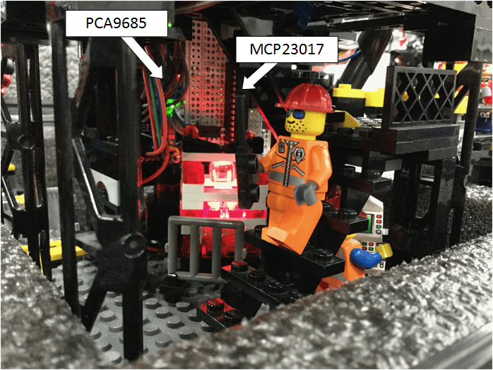
The Raspberry Pi is connected to the chips using I2C, which requires only two wires connected to the Pi. There are additional connectors for 5V power to the chips, and separate 5V power to the lights.

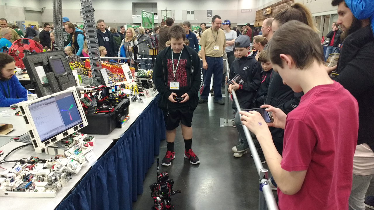
The robot started each day parked behind his fence.
As soon as the crowds arrived, we enjoyed demonstrating what our creation can do. It was nice to see the kids understand the difference between a remote control machine (such as when we were driving it with the XBox remote) and a robot (such as when it was driving itself around using the sensor readings to navigate).
Thanks to the folks at Beyond the Brick for listening to my story about what we built for Brick Cascades 2017.